

Understanding the difference between a Spectacle Blinds and a Line Blank is essential for ensuring safety and functionality in piping systems.
Spectacle Blinds ( also called Spectacle Blanks or Figure-8 Blanks):
Purpose: A Spectacle Blind is a device used to either fully block or allow the flow in a piping/pipeline. It is designed with a metal plate that can be rotated to either block the line or allow flow, ensuring easy maintenance and operation.
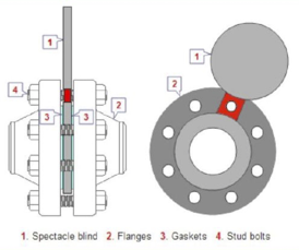
Structure:
One side is a solid disc (the “blind” or “spade”) – this is used to completely block off flow.
The other side is a ring (the “spacer”) – this allows flow through the pipe.
Surface finished:
All gasket mating surfaces need to be serrated in a concentric (circles inside circles) or spiral (like a groove on a record) pattern to provide the proper surface to seal preventing a leak path. Gaskets grooves for RTJ rings are more suitable for higher pressures.
Application: Commonly used in piping systems where frequent changes between open and closed flow states are required, such as in isolation or maintenance operations.
Line Blinds (also called Line Blanks):
Purpose: A Line Blind is a static, non-rotating device used to fully isolate a section of the piping, providing a permanent or semi-permanent block. It is used when no flow is desired between two sections of the piping.
Application: Typically used in long-term isolation tasks or in systems where flow must be completely shut off for safety or operational reasons.
ASME B16.48 – Line Blanks
Line Blanks means figure-8 blanks, paddle blanks, and paddle spacers)
(size 1/2″ to 24″, Classes: 150, 300, 600, 900, 1500, and 2500)
- Figure-8-Blank (also called spectacle blank > see above):
is a pressure retaining plate with one solid end and one open end and connected with a web or tie bar; - Paddle Blank
A paddle blank is similar to the solid end of a figure-8 blank. It has a plain radial handle. It is generally used in conjunction with a paddle spacer in large size (NPS 12 – 24). - Paddle Spacer
A paddle spacer is a similar to the open end of figure 8 blank. it has plain radial handle. It is generally used in conjunction with a paddle blank
ASME B16.48 for operating line blanks in size NPS 1/2″ through NPS 24 for installation between ASME B16.5 flanges in the 150, 300, 600, 900, 1500 and 2500 pressure classes and covers requirements for
- design (facings, facing finish)
- pressure-temperature ratings,
- materials
- dimensions
- tolerances
- marking
- testing
Blanks should be made from a plate or forging specification, approved for use by ASME B31.3 or other design codes, of essentially the same chemical composition as the mating flanges and piping involved.
Spectacle Blanks referred in piping code ASME B31.1
| ASME B31.1 refer to Line Blanks | Listed Blanks requirements | Alternate requirements for not listed blanks | Remarks |
|---|---|---|---|
| Chapter II para. 108.2 | Table 126.1-1: Line Blanks ASME B16.48 | Design acc. to para. 104.5.3 Figure 104.5.3-1 | Attachment of a welded flat permanent blank with only a single fillet weld is not permitted. |
Spectacle Blanks referred in piping code ASME B31.3
| Service | ASME B31.3 refer for Line Blanks | Listed Blanks requirements | Alternate requirements for not listed Blanks | Remarks |
|---|---|---|---|---|
| Normal Fluid Service | Chapter II par. 308.1 | Table 326.1.1-1: Line Blanks ASME B16.48 | para. 302.2.3 (see Note 1) | excepts as stated elsewhere in par. 308 |
| Category M Fluid | Chapter VIII para. M308 > par. 308.1 | Table 326.1.1-1: Line Blanks ASME B16.48 | para. 302.2.3 (see Note 1) | M308.5: All blanks shall be marked with material, rating, and size; |
| High pressure | Chapter IX para. K304.5.3 para. K308.5 | – | Design: K304.5.3 Figure K304.5.3-1 | K308.5: Blanks shall have a marking, identifying material, pressure–temperature rating, and size, that is visible after installation: K304.5.3: for calculation use E=1,0; for definition of c and S see para. K304.1.1; |
| High purity piping | Chapter X par. U304 par. U308 | – | Design: U304.5.3 Figure U304.5.3-1 | – |
Note 1 (see para. 302.2.3):
a) The material shall comply with para. 323.
b) The designer shall be satisfied that the design is suitable for the intended service.
c) Pressure–temperature ratings shall be established in accordance with the rules in para. 304;
Installation
Blanks ideally should be located in horizontal lines to ease their installation andremoval. Blanks should not be used in vertical water and steam lines in climateswhere danger of freezing exists. The use of figure-8 blanks obviously ensures that the companion spacer is onhand when needed (and vice versa). However, these are difficult to handle in the larger sizes [i.e., above NPS 12 (DN 300)], and instead separate spacers and blanks are used.
